Your first project
From an empty library to a PDF. Watch in a few minutes how you draw a plan, build a distribution board and get a single-line diagram.
The video
The video shows a complete project from start to finish: a kitchen with a double outlet, a switch and a light point. Below the video are the same steps as text, with a link to the page that goes deeper.
Creating a project
Volter opens in the library. All your projects will live here.
- Click New project.
- Enter your customer's name and the address of the installation.
- The next two steps hold your own details and those of the installation. You can complete them later.
- Click Create project. The project opens.
More in The library.
Drawing the plan
You start on the floor plan. That is the layout of the home.
- Click Build on the left. Draw wall is already selected.
- Drag from one corner to the next. Each drag is one wall. While you drag, you see the length.
- If you want an exact size, click the wall and type the length.
- In the same menu, choose Place door and click a wall. Do the same with Place window.
- Choose Assign room and click anywhere inside the walls. The room gets a name, and you change it with a double click. The area is shown below it.
More in Drawing walls and rooms and Doors and windows.
Placing and connecting symbols
- Choose Place symbol on the left. The Symbols panel opens, with the symbols per group.
- Open the group Outlets and choose an outlet. Set Quantity to two and click against the wall. That is a double outlet.
- In the same way, place a switch next to the door and a light point in the middle of the room.
- Choose Draw connection. Click the switch and then the light point. Now Volter knows they belong together.
More in Placing symbols and Connecting symbols.
Building the distribution board
- Open the Distribution board tab. A new project has no board yet, so the Set up main board window opens.
- Fill in the values of the main RCD and click Create.
- A home needs an RCD of 30 mA. Click Add row and choose RCD.
- Then add a circuit breaker and name it Lighting. Under Behind RCD, choose the new RCD.
- Do the same for the outlets.
Each circuit breaker is a circuit. Volter gives them a letter, in the order of the rail.
In the video the circuit breaker of the outlets gets a wire size of 1.5 mm² on purpose. That is too thin, and further on you see what Volter does with it.
More in The distribution board.
Assigning circuits
Back on the floor plan, the symbols have no circuit yet.
- Choose Assign circuit on the left.
- In the Circuits list, click Lighting and then the switch. The light point comes along, because they are connected.
- Click the Outlets circuit and then the outlet.
More in Assigning circuits.
The single-line diagram and the AREI check
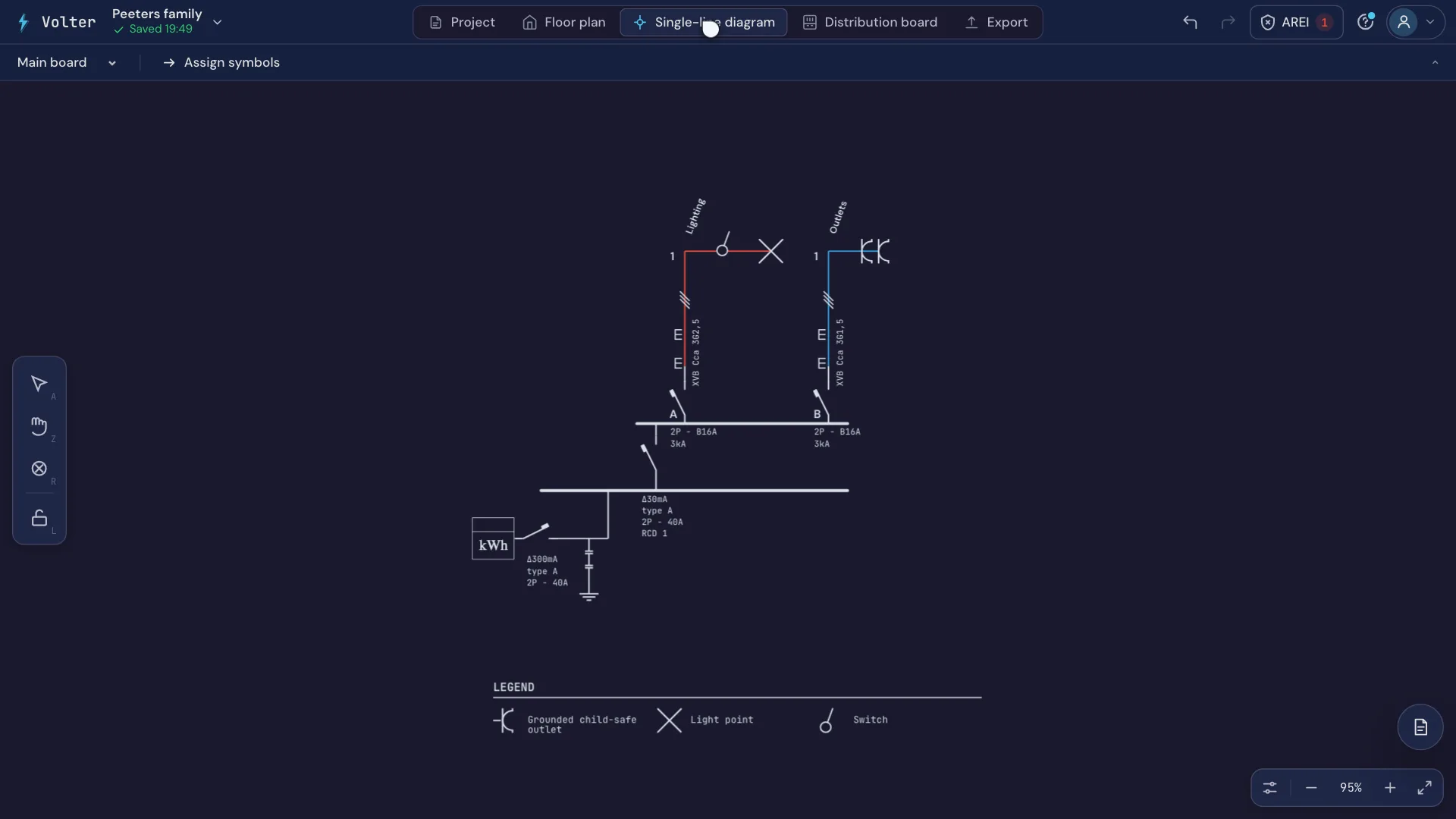
Open the Single-line diagram tab. It is already there. You did not have to draw it yourself: Volter builds it automatically from the data of the floor plan and the distribution board.
Each circuit is a branch. The switch comes before the light point, because you connected them.
At the top right is the AREI check. In the video it reports an error: outlets require wire of at least 2.5 mm². That is the wire size that was chosen too thin a moment ago.
- Click the message to read what is wrong.
- Open the distribution board, click the circuit breaker and set the wire size to 2.5. The error is gone.
This is how you remove errors before the inspection.
The file as a PDF
- Open the Export tab and choose PDF. Volter makes a preview of the pages.
- Click Create PDF to save the file.
The file includes the floor plan and the single-line diagram with its legend, among other things.
More in Export a PDF.
What comes next
Those are the basics. These pages take you further:
- Importing a plan: draw over a building plan.
- Push buttons and home automation: draw an installation with home automation.
- Sharing the diagram with the client: give your customer a link to the diagram.
Valid for Volter 1.3.0